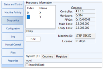
I-Mark I/O Mapping
The First word of the Input bits is the I-Mark Status Word and the First word of the Outputs is the Control Word of I-Mark. Here is the mapping for what bit is which function according to I-Mark’s Inputs and Outputs.
| I-Mark Inputs | I-Mark Outputs | |||||
| Start | EtherNetIP: 0 | Bit 1 | Ready | EtherNetIP: 0 | Bit 1 | |
| Reset | EtherNetIP: 1 | Bit 2 | Marking | EtherNetIP: 1 | Bit 2 | |
| Program Select 1 | EtherNetIP: 2 | Bit 4 | Completed | EtherNetIP: 2 | Bit 4 | |
| Program Select 2 | EtherNetIP: 3 | Bit 8 | Fault | EtherNetIP: 3 | Bit 8 | |
| Program Select 3 | EtherNetIP: 4 | Bit 16 | ||||
| Program Select 4 | EtherNetIP: 5 | Bit 32 | ||||
| Program Select 5 | EtherNetIP: 6 | Bit 64 | ||||
The General sequence is as follows.
For the Program selection you can map whatever program you’d like to the program select bit you desire using the I-Mark software. Those bits can be left HIGH all the time and when I-Mark receives the Start bit it will examine the program select bits and call up the appropriate program for marking. Once the marking begins the Ready status bit will drop out and the Marking bit will come high. When the marking has finished the Marking, bit will drop low and the Completed bit will come high.
The default time for the Completed bit is 250ms, this can be a little short for some communications so as an interlock of sorts, we programmed in the functionality to handshake the Start and Completed bits as an interlock. So, if you leave the Start bit on for the entire marking process, when the Completed goes HIGH it will remain HIGH until the Start signal input goes LOW.
Most customers however do not experience any issues with catching the completed bit so a common programming practice I’ve noticed is just turning on the Start until the Ready drops low or the Marking goes high. Then set a memory when the Completed goes high but also program a timer as a watchdog to ensure that marking finishes in the expected time.
If at any time there is a fault during the marking, the controller will turn HIGH the Faulted bit. Typically toggling the Reset bit to the marker for 250ms will clear the fault and send the marking head back to home. The Reset bit can also be used as a Pseudo Abort function. If the marking has started and the controller receives the Reset input, it will abort the current marking process. A second input after the Faulted bit has gone High will cause the system to clear the fault and return the marking head home.


